
3D Printing Tolerances by Process

Dimensional accuracy is one of the most common questions engineers ask before ordering a 3D-printed part.
Typical questions include:
- Can this bore hold ±0.1 mm?
- Will two MJF housing halves fit together?
- How much clearance should be added to a sliding feature?
- Will a large SLA enclosure remain flat after curing?
- Can an SLM bearing seat be printed to final size?
- Is FDM accurate enough for a manufacturing fixture?
There is no single tolerance value that applies to all 3D printing processes, materials and geometries.
Published machine specifications are useful, but they do not automatically describe the finished tolerance of every feature on a customer part. Final dimensions are influenced by geometry, orientation, material, build position, thermal history, support strategy and post-processing.
The practical rule is:
Treat published tolerances as process capability guidelines, not unconditional guarantees for every CAD feature.
When a dimension controls sealing, bearing fit, alignment, pressure, motion or assembly, identify it as critical and review it separately.
Key Takeaways
- SLA generally provides strong accuracy and fine detail for small and medium resin prototypes, but post-curing and support layout can affect final dimensions.
- MJF offers stable dimensional performance for functional nylon parts and repeated production, especially when geometry and cooling are well controlled.
- SLS is reliable for complex nylon parts, but thermal shrinkage, build position and large flat geometry require careful review.
- Industrial FDM can produce dimensionally repeatable functional parts, but layer direction, bead width, shrinkage and material affect feature accuracy.
- SLM can produce accurate near-net-shape metal parts, but precision bores, sealing surfaces and datum faces commonly require CNC machining.
- Hole diameter, flatness, roundness and position tolerance should not be assumed from a general linear tolerance.
- Larger parts usually require percentage-based tolerance rather than one fixed value.
- Tighter tolerances increase inspection, compensation and post-processing requirements.
- A drawing should distinguish critical dimensions from general dimensions.
- CNC machining remains the preferred secondary process when a printed part requires precision interfaces.
FabNow3D supports SLM, MJF, SLS, SLA and FDM through its industrial 3D printing service.
Representative Published Accuracy Examples
The following values are useful as general reference points, but they should not be interpreted as FabNow3D guarantees for every part.
| Process | Representative published example | Important limitation |
|---|---|---|
| SLA | Approximately ±0.15% to ±0.3% depending on feature size and system | Resin, support, orientation and post-curing matter |
| MJF | Approximately ±0.2 mm for some smaller PA12 parts, with percentage-based tolerance for larger dimensions | Geometry, wall thickness and cooling affect results |
| SLS | A published Fuse Series example states ±0.5% or 0.3 mm in XY, whichever is greater | Z-axis and large thermal sections may require wider tolerance |
| Industrial FDM | Some industrial systems publish approximately ±0.2 mm or ±0.002 mm/mm | Z may include an additional layer-height allowance |
| SLM | Machine- and alloy-dependent near-net-shape accuracy | Precision interfaces normally require machining |
Formlabs publishes size-dependent SLA accuracy examples and separately reports Fuse Series SLS tolerances of ±0.5% or 0.3 mm in XY and ±1% or 0.6 mm in Z. HP has published PA12 MJF examples around ±0.2 mm for certain part ranges, while Stratasys industrial FDM systems publish machine-specific accuracy formulas such as ±0.2 mm or ±0.002 mm/mm. These figures demonstrate why the machine, material, geometry and measurement method must always be stated.
1. Accuracy, Precision, Resolution and Tolerance Are Different
These terms are often used interchangeably, but they describe different manufacturing characteristics.
Accuracy
Accuracy describes how closely a measured dimension matches the CAD nominal dimension.
A 20.00 mm feature measured at 20.08 mm has a dimensional error of +0.08 mm.
Precision or repeatability
Precision describes how consistently the same result is produced.
A process may repeatedly produce a 20.08 mm feature. That process is repeatable, even though it is not centred on the 20.00 mm target.
Repeatability is especially important for production orders because compensation can sometimes correct a stable dimensional offset. Random variation is more difficult to control.
Resolution
Resolution describes the smallest controllable movement, pixel, laser spot, voxel, bead or layer increment of the system.
High resolution does not guarantee equivalent part accuracy.
A printer with a very small pixel or layer height may still produce dimensional variation due to shrinkage, exposure, thermal distortion, supports or material behaviour.
Stratasys specifically distinguishes resolution from manufacturing accuracy and repeatability in its FDM guidance.
Tolerance
Tolerance is the acceptable variation allowed by the drawing or specification.
For example:
20.00 ±0.20 mmThe part is acceptable between 19.80 and 20.20 mm.
Tolerance is therefore a design requirement, while accuracy and repeatability describe manufacturing performance.
2. Why One General Tolerance Is Not Enough
A statement such as “this process can achieve ±0.2 mm” is incomplete.
The same part may contain:
- An external length
- A vertical height
- A horizontal hole
- A thin wall
- A broad flat face
- A snap-fit slot
- A cylindrical boss
- A sealing surface
These features do not necessarily hold the same tolerance.
A printer may control an external dimension well while producing an undersized hole or a warped flat surface.
The drawing should therefore distinguish between:
- Linear dimensions
- Hole diameter
- Position
- Flatness
- Perpendicularity
- Roundness
- Wall thickness
- Surface roughness
- Assembly clearance
General tolerances are suitable for non-critical geometry.
Functional interfaces should be identified separately.

3. SLA Tolerances
SLA uses light to cure liquid photopolymer resin layer by layer.
It is commonly selected for:
- Appearance models
- Fine-detail prototypes
- Small housings
- Master patterns
- Dental and medical models
- Transparent parts
- Complex visual geometry
SLA can provide excellent detail and relatively smooth surfaces. Formlabs publishes representative XY tolerance examples ranging from approximately ±0.15% to ±0.3%, depending on feature size, resin and printer. Its Form 4L documentation also cites ±0.15% XY dimensional tolerance for suitable assemblies.
However, SLA tolerance depends on more than pixel size or laser spot size.
Main SLA tolerance factors
- Part orientation
- Support placement
- Resin type
- Exposure compensation
- Wall thickness
- Wash time
- Post-curing
- Internal stress
- Large flat surfaces
- Measurement after curing
A resin part may change dimension slightly during post-curing. Thin walls and broad unsupported areas are more sensitive than compact, balanced geometry.
Support contact can also affect local surface form. A supported face may require sanding, which can remove material and change the final dimension.
SLA holes and mating features
Small holes may print undersize because of light exposure, resin drainage and cleaning limitations.
For mating features:
- Add realistic assembly clearance.
- Avoid relying on nominal zero-clearance CAD.
- Keep critical holes accessible for drilling or reaming.
- Use inserts for repeated threaded assembly.
- Measure the part after the full curing process.
Choose SLA when visual quality and fine detail are more important than production-material behaviour.
For functional parts requiring stock thermoplastic or metal properties, compare SLA with precision CNC machining.
4. MJF Tolerances
MJF produces nylon parts by selectively applying agents to a powder bed and fusing the complete layer with thermal energy.
It is widely used for:
- PA12 housings
- Brackets
- Clips
- Ducts
- Electrical components
- Jigs and fixtures
- Repeated low-volume production
- End-use nylon parts
HP has published dimensional accuracy examples around ±0.2 mm for certain PA12 parts below 100 mm and percentage-based values for larger dimensions. These examples are useful, but they are tied to specific geometries, materials, machines and finishing conditions.
Main MJF tolerance factors
- Part size
- Wall thickness
- Build position
- Packing density
- Thermal mass
- Cooling rate
- Material
- Orientation
- Bead blasting
- Dyeing or coating
MJF does not require conventional support structures, but this does not eliminate distortion.
Large flat panels, uneven wall sections and concentrated thermal mass can still warp during heating and cooling.
MJF holes
Printed holes may be smaller than the nominal CAD diameter, particularly when they are small, deep or oriented unfavourably.
Critical holes may require:
- Additional design clearance
- Printing undersize followed by drilling
- Reaming
- Thread tapping
- Metal inserts
MJF is often a strong choice for assemblies because it provides good dimensional repeatability across complex nylon parts. However, a test fit should still be validated before approving a large production batch.
5. SLS Tolerances
SLS uses a laser to fuse polymer powder selectively.
It shares several advantages with MJF:
- No conventional support structures
- Complex geometry
- Nested production
- Functional nylon materials
- Internal passages
- Low-volume production
A Formlabs dimensional study reports a standard Fuse Series Nylon 12 tolerance of ±0.5% or 0.3 mm in XY, whichever is greater, and ±1% or 0.6 mm in Z. This is a system-specific published example rather than a universal SLS specification.
Main SLS tolerance factors
- Powder temperature
- Thermal uniformity
- Cooling time
- Powder refresh ratio
- Part location
- Orientation
- Wall thickness
- Large cross-sections
- Material condition
- Depowdering and finishing
Thermal control is central to SLS accuracy because the complete powder bed remains close to the material’s sintering temperature. EOS identifies thermal stability as a key factor in SLS production accuracy and repeatability.
MJF vs SLS tolerance
Neither process is automatically more accurate for every part.
MJF may provide strong consistency for dense PA12 production builds, while SLS capability varies according to machine generation, laser system, material and thermal control.
The better choice depends on:
- Material requirement
- Colour
- Surface finish
- Part size
- Quantity
- Geometry
- Supplier capability
- Inspection requirement
For a tolerance-critical nylon assembly, review the actual CAD geometry rather than selecting only from a general comparison chart.
6. FDM Tolerances
FDM extrudes thermoplastic bead paths layer by layer.
It is commonly used for:
- Functional prototypes
- Jigs and fixtures
- Large components
- Tooling
- ABS and ASA parts
- High-performance thermoplastics
- Economical concept models
Industrial FDM systems can provide good repeatability, but their accuracy depends strongly on machine class and material.
For example, Stratasys publishes approximately:
- ±0.2 mm or ±0.002 mm/mm for some F370-class systems
- ±0.127 mm or ±0.0015 mm/mm for the Fortus 450mc
- Additional Z tolerance related to layer height on some systems
These are system-specific values, not universal values for every FDM printer.
Main FDM tolerance factors
- Nozzle diameter
- Bead width
- Layer height
- Material shrinkage
- Chamber temperature
- Build orientation
- Support contact
- Raster strategy
- Moisture
- Large flat geometry
FDM is anisotropic in both mechanical and dimensional behaviour.
A dimension printed in XY may behave differently from one accumulated through many Z layers.
FDM holes and slots
Small vertical holes often print undersize because the bead path cannot reproduce a perfect circle at small scale.
Horizontal holes may sag or require support.
For critical features:
- Add machining allowance.
- Drill or ream after printing.
- Use threaded inserts.
- Avoid excessively thin walls.
- Keep tolerance-critical faces accessible.
FDM is highly suitable for fixtures and production tools when tolerances are realistic and critical interfaces are machined or fitted with hardware.
7. SLM Metal Tolerances
SLM, also classified as laser powder bed fusion of metals, produces near-net-shape metal components.
It is selected for:
- Internal cooling channels
- Lightweight structures
- Consolidated assemblies
- Complex metal manifolds
- Aerospace components
- Medical components
- Low-volume metal production
SLM dimensional accuracy depends on:
- Alloy
- Build orientation
- Support strategy
- Thermal gradients
- Residual stress
- Part size
- Wall thickness
- Heat treatment
- Plate removal
- Surface finishing
The as-printed part may be suitable for non-critical external geometry, but precision interfaces commonly require secondary machining.
ISO/ASTM 52902:2023 addresses geometric capability assessment using test artefacts, while ISO/ASTM 52908:2023 covers qualification, post-processing, inspection and testing of powder-bed-fused metal parts. These standards reinforce that geometric capability must be evaluated through a controlled process rather than assumed from one nominal machine figure.
SLM features commonly machined
- Bearing seats
- Sealing faces
- O-ring grooves
- Datum faces
- Threaded holes
- Precision bores
- Press fits
- Valve seats
- Mounting interfaces
The preferred strategy is usually:
- Print near net shape.
- Stress relieve the component.
- Remove it from the build plate.
- Machine critical interfaces.
- Inspect against the engineering drawing.
This hybrid route preserves additive geometry while delivering CNC-level precision where required.
For deeper design guidance, see the SLM metal 3D printing guide.
8. Why Holes Often Print Undersize
Hole tolerance is one of the most common additive manufacturing issues.
Possible causes include:
- Stair-stepping
- Melt or exposure compensation
- Polymer shrinkage
- Down-facing roughness
- Unsupported upper arcs
- Powder adhesion
- Tool-path approximation
- Post-processing residue
A printer may produce an accurate external diameter while printing the corresponding internal diameter smaller than nominal.
For non-critical clearance holes, increase the CAD diameter after a validated trial.
For critical holes:
- Print undersize.
- Drill, bore or ream after printing.
- Define the final tolerance on the drawing.
- Specify whether measurement occurs before or after finishing.
Do not assume one offset works for every diameter and orientation.
9. Flatness and Warpage
Flatness is often more difficult than linear size.
A long surface may meet the overall length tolerance but still bow or twist.
High-risk geometry includes:
- Large thin panels
- Broad horizontal surfaces
- Uneven wall thickness
- Heavy sections connected to thin walls
- Asymmetric components
- Long unsupported spans
Process-specific causes include:
- SLA cure stress
- MJF and SLS thermal cooling
- FDM material shrinkage
- SLM residual stress
Improvement strategies include:
- Adding ribs
- Increasing wall thickness
- Balancing the geometry
- Changing orientation
- Dividing the component
- Adding machining stock
- Using a different process
When flatness controls sealing or assembly, specify it as a geometric tolerance rather than relying on the overall linear dimension.
10. Clearance for Assemblies
Two nominally identical CAD surfaces should not be designed with zero clearance when they need to slide, rotate or snap together.
Required clearance depends on:
- Process
- Part size
- Surface roughness
- Orientation
- Material
- Finish
- Required movement
Different interfaces require different design intent:
Fixed alignment
A locating interface may use controlled clearance plus screws or pins.
Sliding fit
A sliding feature needs clearance for both dimensional variation and surface texture.
Snap fit
A snap fit needs clearance, but also depends on material strain, arm length and root radius.
Threaded connection
Printed threads may work at larger sizes and low loads, but inserts or machined threads are more reliable for repeated use.
Always test one assembly before producing a large quantity.

11. Post-Processing Can Change Dimensions
Post-processing should be included in the tolerance plan.
Processes that may affect size include:
- Support removal
- Sanding
- Bead blasting
- Tumbling
- Dyeing
- Painting
- Coating
- Vapour smoothing
- Heat treatment
- HIP
- CNC machining
Painting and coating add material.
Sanding and polishing remove material.
Heat treatment may release residual stress.
Support removal can expose local deformation.
For this reason, the supplier and customer must agree whether the specified tolerance applies:
- As printed
- After heat treatment
- After blasting
- After dyeing
- After coating
- After final machining
FabNow3D’s 3D printing post-processing services can be combined with dimensional inspection according to the final application.
12. How to Specify Tolerances on an RFQ
A good RFQ should include both the CAD model and a technical drawing.
Provide:
- STEP, STP or IGES file
- Quantity
- Process preference
- Material
- General tolerance
- Critical dimensions
- Datum scheme
- Hole requirements
- Thread details
- Flatness requirements
- Surface finish
- Post-processing
- Inspection method
- Required reports
Avoid applying the tightest tolerance to every dimension.
Instead, classify dimensions:
Critical
Affects sealing, motion, alignment, bearing fit, pressure or safety.
Important
Affects assembly but has some adjustment or clearance.
General
Does not materially affect function.
This allows the supplier to choose where printing alone is sufficient and where compensation or machining is necessary.
13. Inspection Methods
Different inspection tools suit different requirements.
Callipers and micrometres
Suitable for accessible linear dimensions, wall thickness and external diameters.
Pin gauges
Useful for hole acceptance.
Height gauge
Useful for relative features and flat reference surfaces.
CMM
Suitable for datum-based dimensional and geometric inspection.
3D scanning
Useful for surface deviation mapping and complex external geometry.
CT scanning
Useful for internal channels and hidden geometry, subject to part size, material density and required resolution.
ISO/ASTM 52902:2023 provides a framework for assessing geometric capability using standardised test artefacts, highlighting the importance of structured measurement rather than relying only on nominal printer resolution.
Process Selection Recommendations
Choose SLA when:
- Fine detail and smooth appearance are priorities.
- The part is a visual or fit-check prototype.
- Small features matter.
- Production-material behaviour is not required.
Choose MJF when:
- Functional PA12 parts are required.
- Assemblies and repeated batches are planned.
- Complex nylon geometry is needed.
- Conventional supports must be avoided.
Choose SLS when:
- Complex nylon parts and nested production are required.
- Material availability favours SLS.
- Surface and tolerance requirements are realistic.
Choose FDM when:
- Economical functional thermoplastic parts are needed.
- The part is large.
- Jigs, fixtures or tooling are the application.
- Critical faces can be machined.
Choose SLM when:
- The part requires metal.
- Geometry cannot be machined conventionally.
- Internal channels or consolidation create value.
- Critical interfaces can be CNC-finished.
Choose CNC machining when:
- Tight tolerances dominate the design.
- The geometry is fully tool-accessible.
- Smooth bores, threads, flatness and precision surfaces are required.
- Production stock material is essential.
Final Recommendation
The most accurate 3D printing process is not automatically the best manufacturing process.
Tolerance selection should begin with the function of the part.
Ask:
- Which dimensions control assembly?
- Which features control sealing?
- Which surfaces require smooth contact?
- Which holes require precision?
- Which dimensions can remain as printed?
- Which features should be machined?
Use printing for geometry, speed, consolidation and low-volume flexibility.
Use CNC machining for precision interfaces.
Use inspection to verify the dimensions that matter.
A realistic tolerance plan reduces cost, avoids unnecessary rework and produces parts that perform as intended.
Upload your CAD file for a tolerance and manufacturability review and include the process, material, quantity, critical dimensions, finish and inspection requirements.
Frequently Asked Questions
Which 3D printing process has the tightest tolerance?
SLA often provides strong detail and dimensional accuracy for small resin parts, while industrial MJF and FDM systems can offer good repeatability for functional components. SLM usually requires CNC finishing for precision metal interfaces. The best process depends on geometry, material and feature type.
Can 3D printing achieve ±0.1 mm?
Some small, stable features may achieve this under controlled conditions, but ±0.1 mm should not be assumed for every process or geometry. Large parts, holes, thin walls and flat surfaces may require wider tolerance or secondary machining.
Why do printed holes come out smaller?
Printed holes may be undersized because of exposure, bead width, powder adhesion, stair-stepping, unsupported geometry or shrinkage. Critical holes should usually be printed undersize and drilled or reamed.
Does layer height determine dimensional accuracy?
No. Layer height affects surface stepping and Z resolution, but final accuracy also depends on calibration, material, orientation, thermal behaviour, support strategy and post-processing.
Are MJF parts more accurate than SLS parts?
MJF may provide strong dimensional consistency for PA12 production parts, but modern SLS systems can also produce accurate and repeatable components. The result depends on machine, material, geometry and process control.
Should SLM parts be machined after printing?
Critical bores, sealing faces, datum surfaces, threaded holes and bearing seats are commonly machined after printing and heat treatment. Non-critical geometry may remain as printed.
How should tolerances be shown on an RFQ?
Provide a technical drawing with general tolerances, critical dimensions, datums, geometric tolerances, threads, surface finish and inspection requirements. Avoid applying tight tolerances to every feature.
Related manufacturing guides
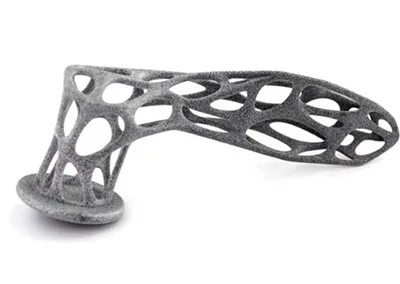
PA11 vs PA12 Nylon for MJF and SLS 3D Printing
PA11 and PA12 are two of the most important engineering nylons used in powder-bed 3D printing. Both can produce support-free functional components,...
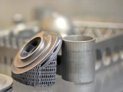
SLM Metal 3D Printing Design Guide
SLM metal 3D printing can produce dense, end-use metal components with internal channels, consolidated assemblies and geometries that would be difficult or...

Quality Control Process at FabNow3D: How Every Order Is Inspected
Quality control at FabNow3D is not a single measurement performed after manufacturing. It is an order-level workflow that begins with the customer’s...