
SLM Metal 3D Printing Design Guide

SLM metal 3D printing can produce dense, end-use metal components with internal channels, consolidated assemblies and geometries that would be difficult or impossible to machine. However, it is not a process in which any finished CAD model can simply be sent to a printer without further manufacturing decisions.
A successful SLM design must control five factors at the same time:
- Heat flow
- Residual stress
- Support accessibility
- Powder removal
- Post-processing
Build orientation affects all five. A part that appears lightweight and efficient in CAD may still be expensive, unstable or impossible to clean if it requires extensive supports, traps metal powder or places a precision surface on a rough down-facing region.
The practical rule is:
Design the component, build orientation and finishing route together.
Do not finish the CAD model first and leave orientation, support removal, heat treatment and machining entirely until production preparation.
SLM is a widely used commercial term. In current ISO terminology, the process falls under laser-based powder bed fusion of metals, or PBF-LB/M. ISO/ASTM 52911-1 provides specific design recommendations for this process and was reviewed and confirmed as current in 2026.
Key Takeaways
- Select a likely build orientation before finalising holes, channels and cosmetic surfaces.
- Treat 45 degrees as an early overhang screening rule, not a guaranteed capability limit.
- Use supports only where they provide necessary anchoring, heat transfer or distortion control.
- Keep support contacts away from sealing faces, bearing seats, threads and inaccessible surfaces.
- Replace difficult horizontal circular channels with teardrop, diamond or angled profiles where function permits.
- Provide practical powder-removal openings for every enclosed passage.
- Add machining stock only to identified critical surfaces.
- Use fillets and gradual section changes to reduce thermal concentration and distortion risk.
- Define heat treatment, support removal, CNC machining and inspection before printing.
For a broader introduction to the process, materials and applications, see the complete SLM metal 3D printing guide.
Quick SLM Design Decision Table
| Design question | Preferred approach | Main reason |
|---|---|---|
| Large flat face parallel to the plate? | Tilt, divide or redesign it | Reduces large uninterrupted layers and distortion risk |
| Precision bore or bearing seat? | Print undersize and machine | Controls diameter, roundness and finish |
| Horizontal circular channel? | Use teardrop or diamond geometry | Reduces unsupported down-facing area |
| Enclosed cavity? | Add accessible powder outlets | Prevents trapped powder |
| Critical sealing surface? | Avoid support contact and add machining stock | Improves flatness and finish |
| Thin rib or wall? | Validate by alloy, height and orientation | Thin features are sensitive to heat and distortion |
| Lattice or hollow section? | Provide cleaning and inspection access | Complex geometry must remain verifiable |
| Support required inside a channel? | Redesign the channel | Internal supports may be impossible to remove |
1. Begin With the Functional Surfaces
The first SLM design decision is not the overhang angle. It is identifying what the finished component must do.
Mark the following directly on the engineering drawing or manufacturing model:
- Datum surfaces
- Sealing faces
- Bearing seats
- Threaded interfaces
- Precision bores
- Mating faces
- Fatigue-critical regions
- Fluid-contact passages
- Cosmetic surfaces
- Areas that cannot tolerate support marks
This classification determines orientation and finishing.
A down-facing SLM surface is generally rougher and less geometrically controlled than an upward-facing or vertical surface. The melt pool above an overhang is partly supported by loose powder rather than solid metal, so heat is removed less effectively and surrounding powder can partially attach to the underside.
A precision sealing face should therefore not be placed in an unfavourable down-facing orientation merely to reduce build height.
Not every surface needs machining. CNC finishing should be reserved for dimensions and finishes that affect function. Specifying every surface as precision-machined reduces the economic and geometric advantages of additive manufacturing.
2. Build Orientation Is the Main DfAM Decision
Build orientation affects:
- Support volume
- Build height
- Heat flow
- Residual stress
- Surface finish
- Material-property direction
- Build-plate utilisation
- Post-processing access
A low build height may shorten machine time, but laying a broad component flat can create large melt areas and greater residual-stress risk. Tilting the same part may increase build height while reducing support contact, improving down-facing geometry and creating a more stable thermal path.
There is rarely one orientation that optimises every requirement.
Before locking the design, compare several orientations and ask:
- Can the component be anchored securely?
- Are critical surfaces facing upward or vertically?
- Can all supports be reached and removed?
- Can powder leave every channel and cavity?
- Does the orientation create large, uninterrupted cross-sections?
- Is the main service load aligned with an acceptable material direction?
- Can multiple parts still be nested efficiently?
Orientation should also account for the recoater. A thin or poorly supported feature that rises, curls or distorts can contact the recoating system and threaten the entire build.
Renishaw’s metal AM guidance therefore treats orientation as a fundamental DfAM decision and recommends comparing several orientations before detailed design is finalised.
3. Understand What Supports Actually Do
SLM supports perform several functions:
- Anchoring local minima and isolated first layers
- Conducting heat away from overhanging regions
- Resisting distortion caused by residual stress
- Stabilising slender features against recoater forces
- Connecting the component to the build plate
EOS similarly identifies heat transfer, residual-stress control and resistance to recoater forces as central reasons for using supports in metal powder bed fusion.
This is why deleting support structures from build-preparation software is not a valid design strategy.
However, excessive supports are also expensive. They increase:
- Build preparation
- Laser exposure time
- Material consumption
- Removal labour
- Surface-finishing requirements
- Risk of damaging thin features
Support design should aim for the minimum necessary support, rather than maximum support or support-free geometry at any cost.
Avoid placing support contacts on:
- Internal channels
- Blind holes
- Sealing surfaces
- Bearing fits
- Fine threads
- Thin cosmetic walls
- Surfaces that cannot be reached after printing
Where substantial support is unavoidable, provide a clear removal route. An accessible sacrificial machining pad may be safer than many small support contacts distributed across a functional surface.

4. Use the 45-Degree Overhang Rule Carefully
A common SLM guideline states that surfaces below approximately 45 degrees to the build plate are likely to require support.
This is useful for early screening, but it is not a universal pass-or-fail specification.
Actual capability depends on:
- Alloy
- Layer thickness
- Machine platform
- Laser and scan parameters
- Local feature length
- Heat accumulation
- Surface-finish requirements
- Orientation relative to the recoater
- Whether the feature is a wall, bridge, hole or broad down-facing surface
A short local overhang may print successfully while a broad surface at the same nominal angle may distort or develop a rough underside.
Renishaw uses 45 degrees as a general design guideline, while newer thermal-management and process-control systems can sometimes produce substantially lower angles. The final limit must therefore be validated for the specific machine, material and qualified parameter set.
Practical redesign options include:
- Replacing a horizontal ledge with a chamfer
- Adding a fillet to form a gradual transition
- Tilting the complete part
- Replacing a flat underside with an angled or curved surface
- Dividing a large overhang into smaller features
- Adding removable sacrificial geometry in an accessible area
Design approval should be based on the complete local geometry—not one angle value.
5. Control Walls, Ribs and Section Changes
There is no single minimum wall thickness that applies to every SLM component.
A short vertical wall, a tall unsupported wall and a broad thin panel behave differently even when their nominal thickness is identical.
Thin features are influenced by:
- Height-to-thickness ratio
- Orientation
- Scan strategy
- Support stiffness
- Alloy behaviour
- Heat concentration
- Stress-relief treatment
- Support-removal forces
- Final polishing or machining
A thin wall may be printable but too fragile to survive support removal. Tall thin walls may deform, while broad thin panels may warp.
Use gradual geometry wherever possible. A sudden transition from a heavy section to a thin wall creates uneven thermal mass and can concentrate residual stress. Fillets, tapers and progressive section changes help distribute heat and stiffness more evenly.
Large uninterrupted cross-sections are also more vulnerable because longer scan paths and greater thermal contraction can increase stress accumulation.
Minimum wall, rib and pin dimensions should be reviewed for the exact alloy and machine. A feature that works reliably in 316L may not provide the same production margin in aluminium, titanium or a crack-sensitive high-temperature alloy.
6. Design Holes for Printability and Final Accuracy
Horizontal circular holes create a down-facing curved region. As the diameter increases, the unsupported upper arc becomes harder to control and may develop distortion or roughness.
Renishaw recommends considering redesign or support for larger lateral holes and shows teardrop or diamond profiles as practical self-supporting alternatives.
Possible strategies include:
- Teardrop-shaped holes
- Diamond-shaped holes
- Angled channel roofs
- Smaller parallel passages
- Printing undersize and finish-machining
- Splitting the component when access is necessary
Critical bearing bores, sealing diameters and precision holes should normally not rely only on the as-printed surface.
Print them with controlled machining stock and finish them after heat treatment and support removal. Non-critical flow passages may be printed directly when their dimensional and roughness requirements allow it.
7. Design Internal Channels for Powder Removal
Internal channels are one of the strongest reasons to choose SLM, but they are also a common source of manufacturing problems.
Every internal passage needs a practical powder-removal route.
A CAD model may show an opening, yet the passage can still be difficult to clean because of:
- Insufficient outlet size
- Blind ends
- Sharp bends
- Long narrow sections
- Internal roughness
- Dead zones
- Branching networks
- Inability to rotate the part effectively
EOS and Solukon recommend providing exit ports, avoiding blind channels and sharp direction changes, and considering the relationship between channel length and diameter during depowdering design.
Review:
- Number and location of outlets
- Outlet accessibility
- Channel length and diameter
- Bends and low points
- Rotation during depowdering
- Cleaning and inspection equipment
- How temporary outlets will be sealed afterward
Unused powder-removal holes may later be plugged, welded, threaded or machined, but this must be included in the process plan.
A hollow part that saves mass but permanently retains powder is not a successful lightweight design.
8. Avoid Local Minima and Internal Supports
A local minimum is a region that begins printing without being connected to the previous layer.
It may appear:
- Beneath an external shelf
- At the top of a lateral hole
- Inside a branching passage
- Under a logo or decorative feature
- Within a lattice transition
These isolated regions require anchoring. Otherwise, the recoater may disturb the first layers and cause a build failure.
The preferred solution is usually to change the geometry so that each new region grows continuously from existing material. This may involve changing an angle, adding a self-supporting transition or replacing a circular feature with a teardrop profile.
Internal supports should be treated as a warning. If support structures cannot be reached by cutting tools, pliers, EDM or machining, they may remain permanently inside the component.
They can then:
- Obstruct flow
- Trap powder
- Release particles during service
- Prevent inspection
- Add uncontrolled mass
Before approving an enclosed design, ask:
How will every support and every volume of loose powder leave the component?
9. Add Machining Allowance to Critical Features
SLM is a near-net-shape process, but it should not be expected to replace precision machining on every functional interface.
Features commonly finished by CNC include:
- Bearing bores
- Precision shafts
- Sealing faces
- O-ring grooves
- Threaded holes
- Datum planes
- Mounting faces
- Press fits
- Valve seats
- Electrical contact surfaces
These features should be printed with controlled stock rather than at their final nominal dimensions.
There is no universal machining allowance. It depends on:
- Alloy
- Part size
- Build orientation
- Expected distortion
- Support-removal route
- Heat treatment
- Workholding method
- Required final tolerance
Do not oversize the entire part unnecessarily.
Machining access must also be designed into the CAD model. Confirm that cutting tools can reach the surface, the component can be clamped safely, and reliable datums remain after plate and support removal.
Hybrid manufacturing is often the most practical route: SLM creates the complex body and internal channels, while precision CNC machining controls the final interfaces.
10. Reduce Residual-Stress and Distortion Risk
Laser powder bed fusion repeatedly heats and cools small regions of metal. Thermal gradients and constrained shrinkage create residual stress.
If the geometry, orientation and support strategy do not control it, the component may:
- Curl at its edges
- Detach from supports
- Distort after plate removal
- Crack during printing
- Deform the build plate
- Lose dimensional accuracy
High-risk geometry includes:
- Large flat cross-sections
- Long uninterrupted melt areas
- Sudden thickness changes
- Sharp internal corners
- Thin walls connected to heavy masses
- Tall asymmetric shapes
- Broad surfaces attached directly to the plate
Useful design actions include adding fillets, breaking up large sections, balancing geometry around the build direction and removing unnecessary bulk.
Build simulation may be appropriate for large, costly or distortion-sensitive parts. Simulation can compare orientation, support layout, thermal behaviour and compensation before production. NIST describes simulation tools for predicting residual stress, distortion, support behaviour and potential recoater interference in laser powder bed fusion.
Stress relief is commonly performed while the component remains attached to the plate so the supports and plate continue to restrain the geometry. The precise sequence must match the alloy and required material condition.

11. Plan Post-Processing Before Printing
The printed geometry is not automatically the finished component.
A typical SLM route may include:
- Controlled cooling
- Powder recovery and depowdering
- Stress-relief heat treatment
- Plate separation by wire EDM or sawing
- Support removal
- Additional heat treatment or HIP, where specified
- Bead blasting, tumbling or polishing
- CNC machining
- Coating or surface treatment
- Dimensional and non-destructive inspection
- Final cleaning and documentation
The sequence matters.
Machining before or after final heat treatment can affect tool wear, dimensional stability and material condition. HIP can reduce certain internal defects, but it cannot correct poor geometry, trapped powder or inaccessible supports.
Polishing improves accessible surfaces but may not reach complex internal passages.
Specify the required final condition in the RFQ rather than requesting only an “as-printed” part. FabNow3D’s metal 3D printing post-processing options can be combined with machining and inspection according to the application.
12. Design Inspection Into the Component
Inspection should be considered during design, particularly when the component contains hidden geometry.
Define:
- Critical dimensions and datums
- General tolerances
- Surface-roughness requirements
- Material and heat-treatment condition
- Density or porosity acceptance
- Channel-cleanliness requirements
- Leak-test pressure and duration
- Certificates and reports
- Sampling plan
- Non-destructive testing requirements
A calliper cannot verify a concealed passage. A CMM can measure external datums but cannot confirm internal powder removal. CT scanning can provide internal information, although feasibility depends on material density, wall thickness, part size and required resolution.
For production parts, test coupons or witness specimens may be required when mechanical properties need verification.
Relevant current standards include ISO/ASTM 52908:2023 for post-processing, inspection and testing of powder-bed-fused metal parts, and ISO/ASTM 52909:2024 for orientation- and location-dependent properties.
SLM Design Review Checklist
Geometry
- Does the design justify SLM through complexity, consolidation, internal channels or weight reduction?
- Have large flat sections and sudden thickness changes been minimised?
- Are thin features strong enough to survive printing and finishing?
Orientation and supports
- Has a preferred orientation been identified?
- Are local minima removed or accessible for support?
- Are critical surfaces protected from support contact?
- Can every support be removed?
Internal features
- Does every cavity have a powder-removal path?
- Are internal supports avoided?
- Can channels be cleaned and inspected?
- Would teardrop or diamond geometry improve printability?
Finishing
- Which surfaces require CNC machining?
- Is suitable machining stock included?
- Are workholding and tool access practical?
- Is the heat-treatment sequence defined?
Quality
- Are material, tolerances and surface requirements stated?
- Are inspection methods suitable for the geometry?
- Is the final acceptance condition clear?
Final Recommendation
Good SLM design is not about removing every support or achieving the thinnest theoretically printable wall.
It is about creating a repeatable manufacturing route from CAD to a clean, inspectable and functional metal component.
Choose SLM when complex geometry, internal flow paths, component consolidation or weight reduction provide measurable value.
Choose CNC machining when the part is simple, fully tool-accessible and dominated by tight tolerances or smooth surfaces.
Use a hybrid route when additive geometry and precision interfaces are both required.
FabNow3D provides industrial SLM metal 3D printing together with machining, heat treatment and finishing support.
Upload your CAD file for an SLM manufacturability review and include the alloy, quantity, critical dimensions, surface requirements, operating environment and inspection needs.
Frequently Asked Questions
What overhang angle can SLM print without support?
Approximately 45 degrees to the build plate is a common screening guideline, but it is not universal. Alloy, machine, layer thickness, feature length, scan strategy and surface requirements affect the actual limit.
Why do SLM parts need supports?
Supports anchor isolated geometry, conduct heat, resist residual-stress distortion and stabilise features against recoater forces. They also connect the component to the build plate.
Should SLM holes be printed to final size?
Critical holes, bearing seats and precision bores should usually be printed undersize and finish-machined. Non-critical holes may be printed directly after reviewing orientation and expected distortion.
How is powder removed from internal channels?
Channels need accessible inlet and outlet openings, smooth transitions and geometry that allows the component to be rotated during depowdering. Blind passages and dead zones should be avoided.
How much machining allowance should be added to an SLM part?
There is no universal allowance. It depends on alloy, size, orientation, distortion, surface condition and machining setup. Add stock only to identified critical surfaces after manufacturing review.
Can SLM print a completely enclosed hollow part?
The geometry may be printable, but a fully enclosed cavity traps powder and cannot be properly cleaned or inspected. Powder-removal openings or a different design are required.
Is HIP required for every SLM component?
No. HIP is application-dependent. It may be specified to reduce internal porosity or support fatigue-critical performance, but it does not replace sound design, qualified processing or appropriate inspection.
Related manufacturing guides
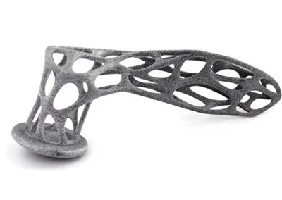
PA11 vs PA12 Nylon for MJF and SLS 3D Printing
PA11 and PA12 are two of the most important engineering nylons used in powder-bed 3D printing. Both can produce support-free functional components,...
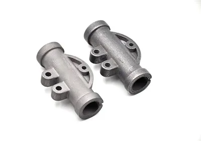
3D Printing Tolerances by Process
Dimensional accuracy is one of the most common questions engineers ask before ordering a 3D-printed part. Typical questions include: There is no...

Quality Control Process at FabNow3D: How Every Order Is Inspected
Quality control at FabNow3D is not a single measurement performed after manufacturing. It is an order-level workflow that begins with the customer’s...